Let's start with the chapter 42 of GPU Gems #1. This chapter, quite mathematical, gives an
overview of the polygonal surface deformation theory. But as always with real time shaders, the problem lies in
the calculation of the per vertex normal vector. Indeed, the change of the vertex position is
a simple operation while its normal calculation maybe quite a complex or even an impossible task in some
cases. The author (Eugene d'Eon) shows us a solution based on Jacobian matrices. In a word,
if the first-order partial derivatives of the surface deformer function are continuous, we can then
compute for each vertex a Jacobian 3x3 matrix that will help us calculating the new normal vector.
If the surface deformer is given by f(x, y, z)=(fx, fy, fz) where fx, fy and fz are three
functions of the x, y, and z variables, the per vertex Jacobian matrix will look like:
| ∂fx/∂x | ∂fx/∂y | ∂fx/∂z |
| ∂fy/∂x | ∂fy/∂y | ∂fy/∂z |
| ∂fz/∂x | ∂fz/∂y | ∂fz/∂z |
where ∂fx/∂x is the derivative of the fx function regarding x.
This is the global idea. For more explanations, please refer to the GPU Gems #1.
With this Jacobian matrix, the calculation of the normal is given by the following relation:
n' = normalize( (J(v)*t) cross (J(v)*b))
where J(v) is the Jacobian matrix at the vertex v, t is the
vertex tangent vector, b the binormal vertex vector (the same used in bump mapping)
and cross the cross product operator.
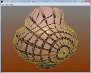
The goal of the following demo is to deform a mesh plane (or a plane polygonal surface)
as shown in the next image:

The function we are going to use to deform this mesh is:
f(x, y, z) = (x, y+sin(f*sqrt(x2+z2) + p), z)
where f is the wave frequency and p its phase. For this function, the Jacobian matrix
at each vertex is:
| 1 | 0 | 0 |
| jac_coef * v.x | 1 | jac_coef * v.z |
| 0 | 0 | 1 |
where v.x and v.z are the vertex x and z coordinates.
jac_coef is equal to:
jac_coef = cos(f*dist + p) / (dist+0.00001);
with
dist = sqrt(v.x2+v.z2)
Software such as Maple can help you to find the literal expressions of the derivatives.
Okay, now the pseudo-theory is assumed, let's go the the shader GLSL implementation.
Only the vertex shader code will be shown, the pixel shader one showing less interest in our case.
You can however refer to the Phong Lighting
tutorial for more details about the pixel shader.
uniform float time;
uniform float frequency;

varying vec3 vNormal;
varying vec4 vVertex;

vec3 computeNormal( vec3 pos,
                    vec3 tangent,
                    vec3 binormal,
                    float phase,
                    float freq )
{
	mat3 J;

	float dist = sqrt(pos.x*pos.x + pos.z*pos.z);
	float jac_coef = cos(freq*dist + phase) / (dist+0.00001);

	// A matrix is an array of column vectors so J[2] is
	// the third column of J.

	J[0][0] = 1.0;
	J[0][1] = jac_coef * pos.x;
	J[0][2] = 0.0;

	J[1][0] = 0.0;
	J[1][1] = 1.0;
	J[1][2] = 0.0;

	J[2][0] = 0.0;
	J[2][1] = jac_coef * pos.z;
	J[2][2] = 1.0;

	vec3 u = J * tangent;
	vec3 v = J * binormal;

	vec3 n = cross(v, u);
	return normalize(n);
}

vec4 displaceVertexFunc( vec4 pos, float phase, float frequency )
{
	vec4 new_pos;

	new_pos.x = pos.x;
	new_pos.z = pos.z;
	new_pos.w = pos.w;

	float dist = sqrt(pos.x*pos.x + pos.z*pos.z);
	new_pos.y = pos.y + 20.0 * sin( frequency * dist + phase );

	return new_pos;
}

void main(void)
{
	vec4 displacedVertex;
	vec3 displacedNormal;

	// 1 - Compute the diplaced position.
	//
	displacedPosition = displaceVertexFunc(gl_Vertex, time*2.0, frequency );

	gl_Position = gl_ModelViewProjectionMatrix * displacedPosition;
	vVertex = gl_ModelViewMatrix * displacedPosition;


	// 2 - Compute the displaced normal
	//

	// if the engine does not provide the tangent vector you
	// can compute it with the following piece of of code:
	//
	vec3 tangent;
	vec3 binormal;

	vec3 c1 = cross(gl_Normal, vec3(0.0, 0.0, 1.0));
	vec3 c2 = cross(gl_Normal, vec3(0.0, 1.0, 0.0));

	if(length(c1)>length(c2))
	{
		tangent = c1;
	}
	else
	{
		tangent = c2;
	}

	tangent = normalize(tangent);

	binormal = cross(gl_Normal, tangent);
	binormal = normalize(binormal);

	displacedNormal = computeNormal( displacedPosition.xyz,
	                                 tangent.xyz,
	                                 binormal,
	                                 time*2.0,
	                                 frequency );

   	vNormal = normalize(gl_NormalMatrix * displacedNormal);
}
Tangent Space Computing:
This vertex shader is a direct implemtation of the previous equations. The little trick, because
there is always a tick, concerns the tangent vector calculation. Usually, we use the texture
coordinates variations to determine accuratly the tangent vector. But in our situation, the following
routine provides quite good results:
vec3 tangent;
	vec3 binormal;

	vec3 c1 = cross(gl_Normal, vec3(0.0, 0.0, 1.0));
	vec3 c2 = cross(gl_Normal, vec3(0.0, 1.0, 0.0));

	if(length(c1)>length(c2))
	{
		tangent = c1;
	}
	else
	{
		tangent = c2;
	}

	tangent = normalize(tangent);

	binormal = cross(gl_Normal, tangent);
	binormal = normalize(binormal);
}
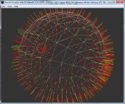
The mesh density has to be taken into account to get a good visual quality.
The previous image showed a 245,000 triangles mesh plane while in the next image,
the mesh plane has only 5,000 triangles:

The main interest to perform the mesh deformation through the GPU capabilities is that
we can apply real time deformations on very dense meshes with an acceptable FPS.
On With my 7800GT, the results are the following:
- 5,000 faces: 580 fps
- 245,000 faces: 170 fps
- 500,000 faces: 90 fps
- 720,000 faces: 64 fps
- 1,280,000 faces: 37 fps
And with a Radeon X700:
- 5,000 faces: 142 fps
- 245,000 faces: 57 fps
- 500,000 faces: 37 fps
- 720,000 faces: 28 fps
- 1,280,000 faces: 17 fps
More than one million faces deformed in real time, only a GPU process can achieve such a job!
At the Demoniak3D demo level, the number of mesh-plane's faces can be set by modifying
the following piece of code in the Surface_Deformer.xml file:
<mesh name="mesh_plane" shape_type="PLANE" render="TRUE"
	lighting="TRUE" use_vbo="TRUE" >
	<position x="0.0" y="25.0" z="0.0" />
	<plane x_size="400.0" z_size="400.0" num_segs_x="350" num_segs_z="350" />
	<attach_material name="mesh_mat" />
</mesh>
The num_segs_x and num_segs_z attributes allow specifying the number
of mesh subdivisions along the X and Z axis.
At the RaptorGL/Win32 demo level, go in the Surface_Deformer project. In the
cDemo.cpp file, find the following line:
m_pMeshPlane->buildPlane( 400.0, 400.0, 800, 800 ); // 1 280 000 faces
The two last parameters of the buildPlane() method specify the number of
mesh subdivisions along the X and Z axis.
More generally, the number of triangles is given by the following relation:
num_triangles = x_subdiv * z_subdiv * 2;
If x_subdiv=350 and z_subdiv=350 then the mesh plane will have 245,000 faces.