4.1 - Spherical Environment Mapping
Spherical Environment Mapping (or SEM) is the first and simpliest of the techniques
allowing to simulate the reflection of the environment on an object's surface. SEM uses only one texture
for the reflection. This texture can be whatever you want but usually we use SEM-ready textures:

Fig. 5 - an example of spheremap
These textures are called spheremaps. The following page allows to download ready to use
spheremaps:
Codemonster - Spheremaps.
You can create yourself your own spheremaps with Photoshop by using the Spherize modifier:

Fig. 6 - base image

Fig. 7 - the spherize modifier

Fig. 8 - the final spheremap
The algorithm behind sphere mapping is as follow:
- 1 - u is the unit vector that goes from the camera to the current vertex: it is the position
of the vertex in eye space and it is also the view vector.
- 2 - n is the vertex normal in eye space.
- 3 - r is the reflected vision vector against the normal n:
r = reflect(u, n)
r = 2 * ( n dot u) * n - u
- 4 - m is an intermediate value:
m = sqrt( r.x2 + r.y2 + (r.z + 1.0)2 )
- 5 - s and t are the final texture coordinates:
s = r.x / m + 0.5
t = r.y / m + 0.5
The following shader is a direct impl�mentation of the previous algorithm:
[Vertex_Shader]

void main()
{
	gl_Position = ftransform();

	gl_TexCoord[0] = gl_MultiTexCoord0;

	vec3 u = normalize( vec3(gl_ModelViewMatrix * gl_Vertex) );
	vec3 n = normalize( gl_NormalMatrix * gl_Normal );
	vec3 r = reflect( u, n );
	float m = 2.0 * sqrt( r.x*r.x + r.y*r.y + (r.z+1.0)*(r.z+1.0) );
	gl_TexCoord[1].s = r.x/m + 0.5;
	gl_TexCoord[1].t = r.y/m + 0.5;
}

[Pixel_Shader]

uniform sampler2D colorMap;
uniform sampler2D envMap;

void main (void)
{
	vec4 color = texture2D( colorMap, gl_TexCoord[0].st);
	vec4 env = texture2D( envMap, gl_TexCoord[1].st);

	gl_FragColor = color + env*0.4;
}
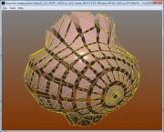
This shader comes from the DEMO_Sphere_Mapping.xml demo:

Fig. 9 - the DEMO_Sphere_Mapping.xml demo
Two textures are used: the base map (colorMap) and the environment map (envMap). gl_TexCoord[0]
holds the colorMap texture coordinates (they are already initialized in the vertex) and gl_TexCoord[1]
contains the envMap texture coordinates that are computed on the fly in the vertex shader.
At the OpenGL level, this shader is equivalent to the following instructions that enable the SEM for
the active texture unit:
glTexGeni(GL_S, GL_TEXTURE_GEN_MODE, GL_SPHERE_MAP);
glTexGeni(GL_T, GL_TEXTURE_GEN_MODE, GL_SPHERE_MAP);
glEnable(GL_TEXTURE_GEN_S);
glEnable(GL_TEXTURE_GEN_T);
SEM is a handy and simple-to-use method but it has a drawback: the reflection slides on the object
and follows the view (it is view-dependent). If the camera moves around the object, the reflection is not
very realistic since it is always the same image that is reflected. We will see later another method
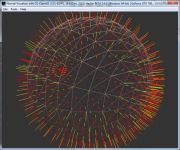
to solve this problem. But in some cases, this feature is interesting like in the following demo:

Fig. 10 - the DEMO_Sphere_Mapping_Metal.xml demo
Another use of this view-dependent feature is the generation of specular highlights.
Indeed, the following texture used in conjunction with the SEM allows to generate really
convincing specular highlights:

Fig. 11 - the specular map

Fig. 12 - the DEMO_Sphere_Mapping_Specular.xml demo
The DEMO_Sphere_Mapping_Specular.xml demo uses the phong shader of the
Point Light in GLSL
tutorial and replaces the specular highlights calculations by a look up in the sphere map:
[Vertex_Shader]

varying vec3 normal, lightDir, eyeVec;

void main()
{
	gl_Position = ftransform();

	vec3 vVertex = vec3(gl_ModelViewMatrix * gl_Vertex);
	lightDir = vec3(gl_LightSource[0].position.xyz - vVertex);
	eyeVec = -vVertex;

	vec3 u = normalize( vVertex );
	normal = normalize( gl_NormalMatrix * gl_Normal );
	vec3 r = reflect( u, normal );
	float m = 2.0 * sqrt( r.x*r.x + r.y*r.y + (r.z+1.0)*(r.z+1.0) );
	gl_TexCoord[0].s = r.x/m + 0.5;
	gl_TexCoord[0].t = r.y/m + 0.5;
}


[Pixel_Shader]

uniform sampler2D envMap;
varying vec3 normal, lightDir, eyeVec;

void main (void)
{
	vec4 final_color =
	(gl_FrontLightModelProduct.sceneColor * gl_FrontMaterial.ambient) +
	(gl_LightSource[0].ambient * gl_FrontMaterial.ambient);

	vec3 N = normalize(normal);
	vec3 L = normalize(lightDir);

	float lambertTerm = dot(N,L);

	if(lambertTerm > 0.0)
	{
		// Diffuse color.
		final_color += gl_LightSource[0].diffuse *
		gl_FrontMaterial.diffuse *
		lambertTerm;

		// Specular color.
		final_color += texture2D( envMap, gl_TexCoord[0].st) *
		lambertTerm;
	}

	gl_FragColor = final_color;
}
4.2 - Dual Paraboloid Environment Mapping
The Dual Paraboloid Environment Mapping technique (or DPEM) is somewhat similar
to the SEM one. The SEM encodes the whole scene in a single texture while DPEM uses two textures:
one for the Z-positive half-space and the other for the Z-negative half-space.
The main advantage of DPEM compared to SEM is the independence of the reflection
regarding to the view (DPEM is view-independent) that allows to create realistic
reflection of the environment on the objects's surface.
The following both papers discuss the mathematic details of the DPEM:
The DEMO_Dual Paraboloid_Mapping.xml demo shows DPEM in action:

Fig. 13 - the DEMO_Dual Paraboloid_Mapping.xml demo
And here is the DPEM shader from the DEMO_Dual Paraboloid_Mapping.xml demo:
[Vertex_Shader]

uniform mat4 ModelWorld4x4;
uniform vec3 CameraPos;

varying vec3 R;

mat3 GetLinearPart( mat4 m )
{
	mat3 result;

	result[0][0] = m[0][0];
	result[0][1] = m[0][1];
	result[0][2] = m[0][2];

	result[1][0] = m[1][0];
	result[1][1] = m[1][1];
	result[1][2] = m[1][2];

	result[2][0] = m[2][0];
	result[2][1] = m[2][1];
	result[2][2] = m[2][2];

	return result;
}

void main()
{
	gl_Position = ftransform();

	mat3 ModelWorld3x3 = GetLinearPart( ModelWorld4x4 );

	// find world space position.
	vec4 WorldPos = ModelWorld4x4 *  gl_Vertex;

	// find world space normal.
	vec3 N = normalize( ModelWorld3x3 * gl_Normal );

	// find world space eye vector.
	vec3 E = normalize( WorldPos.xyz - CameraPos.xyz );

	// calculate the reflection vector in world space.
	R = reflect( E, N );
}

[Pixel_Shader]

uniform sampler2D frontMap;
uniform sampler2D backMap;

varying vec3 R;

void main (void)
{
	vec4 output_color;

	vec3 vR = normalize(R);

	// Select the front or back env map according to the sign of vR.z.
	if(vR.z>0.0)
	{
		// calculate the forward paraboloid map texture coordinates
		vec2 frontUV;
		frontUV = (vR.xy / (2.0*(1.0 + vR.z))) + 0.5;
		output_color = texture2D( frontMap, frontUV );
	}
	else
	{
		// calculate the backward paraboloid map texture coordinates
		vec2 backUV;
		backUV = (vR.xy / (2.0*(1.0 - vR.z))) + 0.5;
		output_color = texture2D( backMap, backUV );
	}

	gl_FragColor = output_color;
}
The reflection vector R is calculated in the world space. That allows this independence
regarding to the camera contrary to the SEM. To do this, we have to pass to the vertex shader
the object's absolute transformation matrix (ModelWorld4x4). This matrix contains the
object's transformation (the torus) regarding to the world space. If the object is positioned
in {0.0, 0.0, 0.0} and does not have orientation, the transformation matrix is equal to the
identity one (useful to test one's vertex shader).
Then, a test is done in the pixel shader to determine the right texture (front or back).
An optimization could be to merge both textures in a single one bigger and play with the
t texture coordinate offset in order to access to the right part (up or down) of the
texture.
The GetLinearPart() function is used to convert a 4x4 matrix to a 3x3 matrix by
extracting the upper-left 3x3 matrix from the 4x4 one. This function can be also replaced
by a GLSL type conversion but watch out, this trick does not work on ATI boards:
mat3 ModelWorld3x3 = mat3( ModelWorld4x4 );
The following page of the Codemonsters website offers some examples of dual paraboloid maps:
Dual Paraboloid Maps.
4.3 - Cube Environment Mapping
To end up with environment mapping, here is the technique using cubemaps:
the Cube Environment Mapping or CEM. This technique gives the best r�sults but needs
the use of 6 textures.
A cubemap is real type of texture as 2D texture is. A cubemap has 6 faces corresponding to
each of the six half-axis: POS_X, NEG_X, POS_Y, NEG_Y, POS_Z and NEG_Z. A cubemaps is
available as 6 image files. The following page of the Codemonsters website has a huge amount
of ready-to-use cubemaps:
Cube Maps.
As the DPEM is, the CEM is view-independent. All vectors are expressed in world
coordinates. The CEM shader is slightly the same than the DPEM one and here are the changes:
- the sampler for a cubemap is samplerCube.
- the function to fetch cubemap texels is textureCube().
The first parameter is a samplerCube and the second is a XYZ vector that allows the function
textureCube() to select the right face of the cubemap and then to extract the texel.
The functioning of textureCube() could be as follow: the coordinate with the largest magnitude
selects the face. The remaining two coordinates are divided by the absolute value
of the largest coordinate and are mapped to the range [0.0 - 1.0].
Example: the vector R = {0.287, -0.944, 0.164} selects the NEG_Y face. The texture coordinates
{s, t} are calculated as follow: s = (0.287/0.944*0.5) + 0.5 and
t = (0.164/0.944*0.5) + 0.5 then {s, t} = {0.65, 0.58}. The vector R is the same
as for the DPEM.
The DEMO_Cube_Mapping.xml demo shows a textured (color map on texture unit 0)
and cubemapped (cubemap on texture unit 1) torus:

Fig. 14 - the DEMO_Cube_Mapping.xml demo
The CEM shader, from the DEMO_Cube_Mapping.xml demo, is shown hereunder:
[Vertex_Shader]

uniform mat4 ModelWorld4x4;
uniform vec3 CameraPos;

mat3 GetLinearPart( mat4 m )
{
	mat3 result;

	result[0][0] = m[0][0];
	result[0][1] = m[0][1];
	result[0][2] = m[0][2];

	result[1][0] = m[1][0];
	result[1][1] = m[1][1];
	result[1][2] = m[1][2];

	result[2][0] = m[2][0];
	result[2][1] = m[2][1];
	result[2][2] = m[2][2];

	return result;
}

void main()
{
	gl_Position = ftransform();

	// Color map texture coordinates.
	// Increase a little bit the tiling by 2.
	gl_TexCoord[0] = gl_MultiTexCoord0 * 2.0;

	mat3 ModelWorld3x3 = GetLinearPart( ModelWorld4x4 );

	// find world space position.
	vec4 WorldPos = ModelWorld4x4 *  gl_Vertex;

	// find world space normal.
	vec3 N = normalize( ModelWorld3x3 * gl_Normal );

	// find world space eye vector.
	vec3 E = normalize( WorldPos.xyz - CameraPos.xyz );

	// calculate the reflection vector in world space.
	gl_TexCoord[1].xyz = reflect( E, N );
}

[Pixel_Shader]

uniform samplerCube cubeMap;
uniform sampler2D colorMap;

const float reflect_factor = 0.5;

void main (void)
{
	vec4 output_color;

	// Perform a simple 2D texture look up.
	vec3 base_color = texture2D(colorMap, gl_TexCoord[0].xy).rgb;

	// Perform a cube map look up.
	vec3 cube_color = textureCube(cubeMap, gl_TexCoord[1].xyz).rgb;

	// Write the final pixel.
	gl_FragColor = vec4( mix(base_color, cube_color, reflect_factor), 1.0);
}
In this shader we use the texture coordinates of unit 1 (gl_TexCoord[1]) for
passing the reflection vector between the vertex and the pixel shader. In the pixel shader,
the color maps and the cubemap texels are retrieved and are mixed with the mix() function.
mix() is a GLSL function that performs a linear interpolation between two vectors passed
in parameter. If the reflect_factor parameter is equal to 0.0, then gl_FragColor
will be equal to the base color (base_color) and if reflect_factor is equal to
1.0 (full reflection) then gl_FragColor will be equal to the cubemap color.