In
Demoniak3D, each visible element in the 3d scene is an object: a model, a mesh, a light, a hud and a primitive are examples
of object. These objects have all the same structure which is represented by the following diagram:
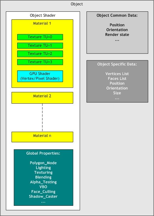
fig.1 - General organization of an object of the 3D scene.An object is composed of 3 main parts:
- A shader (Shader Object)
- Data common to all the objects (Object Common Data)
- Specific data to each type of object (Object Specific Data)
It is necessary to understand the structure of the objects handled by Demoniak3D in order to better use the various available nodes
(or XML elements) for the realization of a HyperGraph. All these concepts are in direct relation with the
oZone3D engine, key-stone
of Demoniak3D.
The
specific data vary according to the type of object: a mesh will have a list of vertices and faces while a light will have
ambient, diffuse and specular components. Each object thus has its own or specific data which will be used during the scene rendering
process.
The
common data are general informations which every object includes, such as its name, its position, its rendering state.
All the objects have jointly a structure called
shader (not to be confused with a vertex or pixel shader!). The shader is a concept
that gathers all the informations and data which will define the final appearance of the object when rendering is displayed on
the screen. A shader is a states machine in the sense that the final rendering output is related to all the states of the shader
at that rendering time. Among the most significant states, one can quote lighting (does the object react to the light?), texturing
(for texture application), blending (mixture of colors), rendering mode of the polygons (wire or solid mode).
A shader consists also of a fundamental element that can be found in almost all available 3d softwares of the market: the
material.
The material is a structure which more precisely defines the physical characteristics of the surface of an object. These
characteristics are mainly used for lighting calculations (ambient, diffuse and specular components). For a detailed explanation of light
and materials, please refer to the
Lighting and Materials. tutorial. A material contains
also textures whose texels (texture element) will modulate the final appearance. It is possible to assign 4 textures per material in
order to get all the multitexturing based effects. But it is necessary that the graphics controller has at least as many textures
units (texture unit or "TU") than the number of textures really attached to a material. In general, all the recent graphics cards
have 4 texture units.
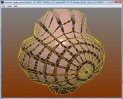
The following image, resulting from tutorial 51, shows a sea-bed with cautsics.
This effect has been made by using 3 textures for the sea-bed material.
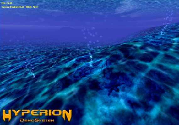
fig.2 - Multitexturing.The material contains also another significant element to increase visual realism or simply to develop graphics effects:
the
vertex pixel shader still called
programmable shader or
GPU shader. It is at this particular level of an object, in the
material, that the developper can attach these famous small pieces of code which make it possible to reprogram the vertex and
pixel processors of the graphics controller. The GPU shaders are regularly used in the Demoniak3D demos. It enhance the visual
quality (per pixel lighting) and accelerate geometrical calculations on the vertices (mesh deformation for example).
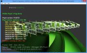
The following image shows the specular reflections calculated in a shader program:
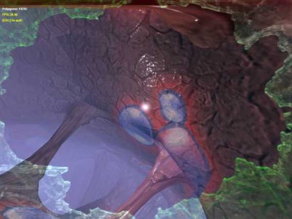
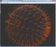
fig.3 - A vertex pixel shader in action.The following image shows a transparent material (resembling glass). The properties of this material are managed by a
GPU shader. In this case, the GPU shader handles the basic physics equations: the reflexion / refraction phenomenon:
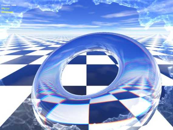
fig.4 - A vertex pixel shader of reflexion / refraction.A shader can contain several materials with no limits except that if too many materials are used for a same mesh,
a fall of performances may occur. An example of borderline case (yet not tested) would be to affect a different material for each
polygon of a mesh featuring 10000 faces.
All the concepts evoked above may directly be found in the nodes of the hypergraphs (shader_program, material, texture mesh...).