The
GLSL,acronym of
OpenGL Shading Language, forms part of the programming languages for the graphics card’s vertex and
pixel processors, for the same reason as the
HLSL of Direct3D or the
Cg of nVidia. The vertex and pixel processors are
processing units, to be found in the GPU (Graphics Processing Unit), which act respectively on the vertices and the pixels. In order not
to repeat what I have already said on the presentation of programmable shaders, please see part 3 of the tutorial on
graphics controllers.
To seriously approach the programming of vertex and pixel shaders in GLSL, it is strongly recommended to equip yourself with
the Orange Book, the reference book as far as GLSL is concerned (de Randi Rost - ISBN: 0-321-19789-5):

Fig. 1 - The reference book on the GLSL languageFor the suite of this tutorial, we will now avail ourselves of the
Demoniak3D platform to
integrate and test our vertex and pixel shaders written in GLSL. You also need a 3D card that tolerates shaders. All the nVidia Geforce
FX 5200 cards and higher or ATI Radeon 9600 cards and higher tolerate GLSL. Of course, the latest version of the graphics drivers from
the manufacturers (Forceware for nVidia et Catalyst for ATI) should be installed.
A little warning: programming vertex and pixel shaders is globally low level programming. Unfortunately, there are
therefore often different comportments between the different 3D cards. The ideal, to code in GLSL and to be assured that one’s code will
work everywhere, is to have 2 machines: one having an nVidia Geforce card and the other an ATI Radeon card... that’s a good start!
Before going further, let us clarify the vocabulary. A vertex shader is a portion of code (a programme) which will be compiled
then run in the vertex processor. Idem for the le pixel shader. A shader (also named
shader program) is the general term for
naming the block formed by a vertex shader and a pixel shader. In OpenGL terminology, the vertex shader is named
vertex program
and the pixel shader is named
fragment program. For the following, I shall more often use vertex shader and pixel shader, which
are, in my opinion, the most common terms to qualify shader programmes.
The different shading languages (GLSL, Cg and HLSL) are fairly close to each other. Therefore the apprenticeship of one of them
permits one to rapidly pass on to another. As far as I am concerned, I often consult the sources in HLSL before converting/adapting them
to my needs in GLSL. This being said, we will now pass on to coding our first shader.
For our first shader, I propose something extremely simple. The aim is to see the structure of a programme in GLSL and
especially to understand the basic functioning of a shader. Once this step accomplished, the door towards the wonderful world of
vertex and pixel shaders is open to you!
A shader programme is composed of two parts:
- the vertex shader code
- the pixel shader code
According to the development platforms, these 2 codes may be found in two distinct files, or within the same. In the case of
Demoniak3D, a shader program (vertex shader + pixel shader) is coded in one file only. But at this point, Demoniak3D offers a greater
flexibility, because we can code our shader directly in XML script, thus saving the management of a large number of files during
voluminous projects.
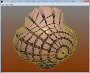
The function of this first shader programme is to uniformly colour a simple mesh plane composed of 4 vertices. Figure 2 shows the
rendering that you will obtain when applying this shader to the mesh.

Fig. 2 - The rendering of our first shaderIn order to understand the following, I advise you to download the accompanying project and to load it into Demoniak3D.
The download is to be found at the bottom of this page.
Before going into the details of the shader code, you must understand what
applying a shader means.
All 3D objects in Demoniak3D are endowed with at least one material. Material is fundamental because it intervenes in the calculations of
the lighting, may have textures and last of all, and it is what is most important for this tutorial, material permits liaison between
a shader programme and a 3D object.
Therefore, and in a word, in order that a shader programme may have an action on a mesh, the shader must be assigned to one of the
materials that form the mesh. In our case, the mesh is composed of one sole material (named plane_mat in XML script). The assignment
of the shader to the material is done in the following manner:
<material name="plane_mat" shader_program_name="simple_color_shader" />
where simple_color_shader is the name of our shader. We find this name again in
the node
shader_program. This node is the central node for the creation
of a shader programme.
2.1 - The vertex shader
Now let us go to the analysis of the vertex shader. The code is the following:
[Vertex_Shader]
void main(void)
{
	gl_Position = ftransform();
}
The first line, [Vertex_Shader], marks the beginning of the vertex shader. Be
careful: there is no standard at this level. Each 3D development environment, each
3D engine, has its own way of marking the beginning of a vertex or pixel
shader. The oZone3D engine, which is hidden in Demoniak3D’s shadow, has chosen
this manner which seemed the most simple, seeing that the same file contains both
the vertex shader’s code and that of the pixel shader.
GLSL syntax is inspired, as many of the present languages, from the venerable C
language. At this moment, the entry point of the vertex shader is the function
main().
It is the first function to be performed; it is as simple as that. The body of
the main function, situated between the two brackets, is reduced to the strict
minimum:
gl_Position = ftransform();
This code line, apparently anodyne, is nevertheless fundamental. In effect it
is mandatory and all vertex shaders should at least contain this function. But
what does it do? In order to reply, we need a little more information.
A vertex shader treats one vertex at a time. Therefore if there are 10000 vertices in our mesh, the vertex processor will perform
the vertex shader 10000 times. A vertex is composed of a number of attributes (vertex attrib): position, texture coordinates, normal
and colour for the most common. The position attribute, or simply the position, is the most important. The coordinates (x, y et z) of
the vertex’s entering position are those which have been given by the 3D artist during the modelling. The vertex’s position is defined
in the local space of the mesh (or object space).
We can now reply to the preceding question: the aim of this vertex shader is to transform the position of the local space
vertex to the 3D space of the camera. It is only in this form that the position of the vertex may be used in the following stages
of the 3D pipeline. In a more detailed manner, the vertex shader will multiply
the position of the vertex entering into the matrix 4x4 model_view_projection. This
matrix is the concatenation of the following three matrices:
- object transformation matrix
- camera viewing matrix
- camera projection matrix
The following code is just as valid:
gl_Position = gl_ModelViewProjectionMatrix * gl_Vertex;
Theoretically, it is supposed to do the same thing. But there may be rendering artefacts due to different implementations of the
OpenGL standard in the graphics cards. The function ftransform() guaranties that the rendering will be the same no matter what the
OpenGL implementation is.
gl_Vertex is a keyword of GLSL language. More exactly, it is one of the numerous variables predefined in GLSL, which permits
direct accession to the different attributes of the entering vertices and pixels. The same goes for
gl_Position.
gl_Vertex represents the entering vertex’s position, whereas gl_Position is that of the outgoing transformed vertex.
A vertex processor only deals with vertices as I mentioned earlier. This is important to understand, as even if a polygon is composed
of 3 or more vertices, the vertex processor will never know it. It even does not know if an entering vertex is part of a polygon.
It is therefore impossible for the vertex shader to undertake such operations as back-face culling because this operation
requires the knowledge of all the vertices composing a side or the normal of this side.
We will see in a future tutorial the use of other attributes of a vertex (normal, colour, texture coordinates, ...).
2.2 - The pixel shader
Let us attack the analysis of the pixel shader. The code is the following:
[Pixel_Shader]
void main (void)
{
	gl_FragColor = vec4(1.0, 0.0, 0.0, 1.0);
}
The structure of the pixel shader is the same as that of the vertex shader. The beginning of the pixel shader is marked
by [Pixel_Shader] and the entry point is defined by the function main(). This pixel shader only does one thing: write
the vector 4D <1.0, 0.0, 0.0, 1.0> in the
gl_FragColor variable.
gl_FragColor is part of the predefined GLSL variables, just like gl_Vertex and
gl_Position. The only aim of a pixel shader is to calculate the value which will be written in gl_FragColor. gl_FragColor
represents the pixel’s final colour in the frame buffer. But beware: certain tests situated after the pixel
processor, such as for the alpha-test, may modify this affirmation. In effect, if the outgoing pixel processor does not pass
the alpha test, it will simply not be written in the frame buffer.
vec4 is one of the numerous types of available data in GLSL. vec4 represents a 4D vector. gl_FragColor is none other than a 4D vector
which contains the 4 colour components of a pixel: Red, Green, Blue et Alpha. In order to accede to the coordinates of the
gl_FragColor vector, nothing more simple as you can see in this following piece of code:
gl_FragColor.r = 1.0;
gl_FragColor.g = 0.0;
gl_FragColor.b = 0.0;
gl_FragColor.a = 1.0;
This code has exactly the same effect as the original code. We could also have written the following:
vec4 final_color = vec4(1.0, 0.0, 0.0, 1.0);
gl_FragColor.r = final_color.x;
gl_FragColor.g = final_color.y;
gl_FragColor.b = final_color.z;
gl_FragColor.a = final_color.w;
GLSL offers us a great liberty of expression!
What a lot of explanations for this simple shader! Maybe you are beginning to
understand the myth which says that the programming of shaders is complex. It
is complex, which is a fact. But it obliges us to veritably understand what
happens under the bonnet of our dear (and expensive!) graphics cards. This is
the price to pay to be able to create advanced shaders and be able to let your
imagination flow freely...
Here, finally, is a list of useful links:
- 3DLabs Fixed Functionality Shader Tool: this
little tool developed by 3DLabs will permit you to generate the GKSL vertex and pixel shaders which reproduce the functioning of the fixed
Transform & Lighting and Texturing units. Really interesting in order to understand the 3D pipeline...
- nVidia SDK: This SDK contains tens of examples on the GLSL shader prog. To
have in one’s 3D developer toolbox!
- ATI SDK: ATI's SDK is now really cool and well organized (as nVidia!). There are many source codes and good whitpapers on many topics.
As nVidia's sdk, to have in one’s 3D developer toolbox!